CLICK HERE FOR THE MAIN BRITANNIA PICTURES PAGE!
70000 'Britannia' at Crewe - Detailed Photographs taken by Nigel Fraser Ker - 28 May 2000
I am grateful to Doug Hewson for
writing the excellent captions to these pictures - he apologised
for the
little adverts he hid amongst them although now the running of his
business has been taken over by Simon Hudson of The Steam Workshop.
If you're interested
in live steam 5" or 71/4" locomotive, why not take a look at The Steam Workshop's website at http://www.steamworkshop.co.uk.
 1. BR Standard "K" Class Exhaust Steam Injector. The large lagged pipe is the exhaust steam feed from the blast nozzle in the smokebox. |
 2. Same as Number 1. |
 3. Bogie equalising bars and steam operated cylinder cocks. The centre one is the steam chest drain which has a pipe from a tapping on the underside of the steam chest behind the cylinder cleading. The cylinder drains are kept shut with live steam supplied from the drivers valve which is situated on the left of the firebox just under the footplate. (Lost wax castings should be available for these shortly). |
 4. Main front bolster and bogie centre. The side control springs are visible above the front coupled Cannon Axle Box. The pipe on the left is the live steam pipe to the cylinder drain cocks. |
 5. Similar to 4 above. |
 6. Front End. Note the pipe arrangement to the vacuum hose connection. This is the standard arrangement for all BR Standard engines (Would you believe!). The ribbed hose behind the vacuum pipe is to the AWS. (Automatic Warning System for signals). Note the stay to the front step. |
 7. Front of bogie and guard iron. |
 8. Left hand Bogie Pressure Plate. Just under the bearer bracket are the grease pipes from the nipples on the side of the bearer plate to the horn cheeks. |
 9. Right hand side of Bogie. Note single swab box to piston rod and cylinder relief valve. |
 10. Boiler underside. The large pipe diagonally up to the left is the sand box filler with red sand box visible. The pipe sweeping up to the left is from the injector to the right hand clack. |
 11. Boiler, right hand side. The large lagged pipe is the exhaust steam to the injector. |
 12. Boiler, left hand side. |
 13. Boiler, right hand side. |
 14. Brake, right hand side. Note steam sander ejector and pipe work, and , the split cotter in the end of the brake beam. |
 15. Front end. Things worth noting are, the simple lamp irons (Not "brackets" please!), the dimpled buffer steps, and nuts on the outside to fix the buffers in place. This is standard practice on virtually all locos. Note that the steam heat hose is plain rubber and not ribbed. |
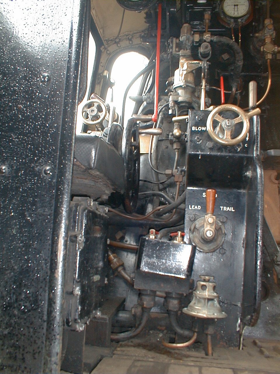
 16. Britannia Cab Centre 1. The red handle is the whistle operating lever and the bottom left wheel is the blower valve on the driver's pedestal. At the top right is the boiler pressure gauge with the carriage warming pressure gauge above and the handwheel to the right is the steam heating valve isolator. The left hand live steam injector valve is just visible to the extreme right and the brown Tufnol handle on the bottom of the pedestal is the sanding valve. |
 17. Britannia Cab Centre 2. To the left of the red whistle valve is the Graduable Steam Brake Valve (As supplied by Dave Noble) with the Driver's Vacuum Brake valve on top of pedestal (as supplied by D. Hewson Models) and the fire hole flap in the centre. |
 18. Britannia Cab Left. The regulator handle is red (Usually black) and to the left in the window are the two steam valves for the large and small vacuum brake ejector. The reverser is of course clearly visible and to the left of the blower is the vacuum reservoir release button. At the base of the pedestal is the isolating valve for the tender steam brake. |
 19. Britannia Cab left 2. The dial on the left is the Speedometer with the AWS indicator black and yellow. The gauge with the two needles is the Vacuum Duplex Gauge with the left hand needle for the train pipe and the right hand one for the reservoir. Also visible is the vacuum operated steam brake valve and the two water gauge frames. |
 20. Britannia Cab Left 3. Again the large and small ejector valves are visible with the reverser and latch (as available from D. Hewson Models). The red drum is the cut off indicator but on BR engines this would have been black with lettering picked out in white. |
Page: 1 2 3 4 5 6